|
ARTICLES & HOW-TOS |
Creating New Ship Drawings from Existing Image Files
Rex Boocock
PART 1: THE BASICS
The purpose of this tutorial is to show a way to convert a digital image to a more accurate drawing using only 2 programs: Photoshop and AutoCAD. If you are starting with a paper plan, this will need to be scanned to convert it into a digital image. Be sure to incorporate the scale ruler in the image.
First we must decide what the drawing is going to be used for. If the purpose is to build a scale model, then a lot of the information on the original drawings will be superfluous. We only want enough information on our new drawing to allow us to construct the model. More detail can be added later if necessary.
1 Prepare image for insertion into CAD package
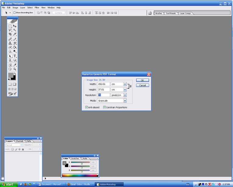
Using Photoshop, import the image using the resolution deemed best for purpose – if using for hull lines, select 50 to 70 pixels/cm, for all other uses 40 to 50 will do. The higher the number, the larger the file size.
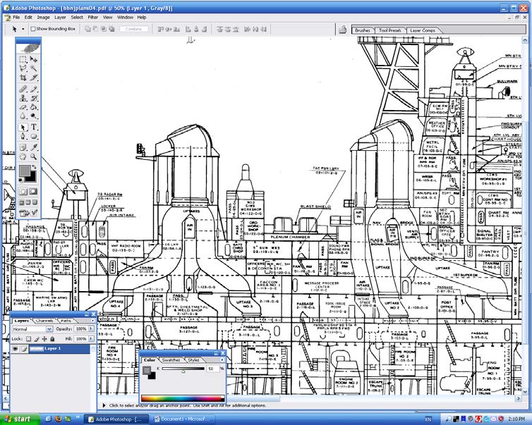
When the image is opened, inspect it very carefully to see quality of the lines and text. They should all be easy to read and clear, Do not bother with scaling, centering or squareness at this stage. Crop the image to show only the part required for the new drawing. If needed, use Photoshop to despeckle and clean the image up, though there is no point in spending a lot of time on this. Make sure the image is easy to understand. A bit of careful work here will save time later on. The example below shows a corrected .pdf image.
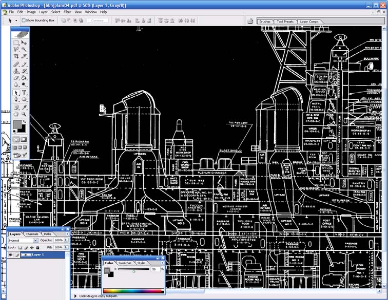
Next, we invert the image – (this changes black to white and vice versa). This will make the images easier to use in AutoCAD as we will add many reference lines and use the line color to identify them. Have a final look at the image – it should look like that shown below – then save (usually in .pdf format, though AutoCAD can import other file types).
2 Insert image to CAD package
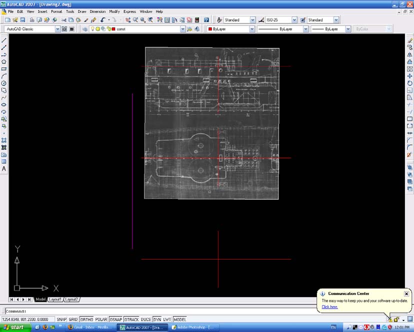
Open AutoCAD and insert the file using insert, raster image reference. Leave insertion point, scale and rotation at the default settings. When the image is inserted, zoom to extents, right click on the image and select draw order, send to back. This ensures that all the new lines we draw will be visible over top of the inserted image.
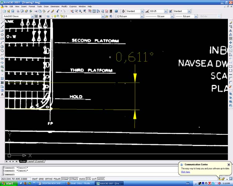
Next, we will rotate and scale the image. Draw an ortho line the length of the image along the base, waterline or wherever it is easy to see. Then draw another line over another long line on the image. Dimension the angle between the two lines. On the example below, the image is rotated 0.611° counterclockwise off center. Rotate the image by that amount to bring it back to being square.
We now have an aligned image, but need to do a little simple math to make it the correct scale. Using the DI command (or draw an overlaying line), measure the distance between 2 known points. Use the longest known line on the image where possible. I typically use station lines. In the example below, the station lines are 4’-0” on center, so by drawing a line from the FP to the AP (a real life distance of 215 stations), we know that the corresponding length of the line should be 215x4 = 860 feet. The measured AutoCAD line we drew is 1319.3006 units long. I use millimeters, so the line should be 860 x 12 x 25.4 long, which is 262,128 mm.
The image needs to be rescaled by a factor of 262,128÷1319.3006, which is 198.687. The original drawing was drawn at a scale of 1:192 so the printing and scanning process has changed the original drawing from 1:192 to 1:199 scale. After scaling up, we now have an image that is 1:1(life size) to the real ship and square to the model space.
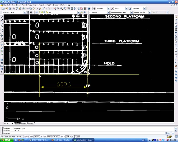
In the example below I have dimensioned between the FP and Station 5, a distance in real life of 20 feet. We now need to move the image to a known point. Use the bottom left hand corner of the image and move it to the 0, 0, 0 point in AutoCAD model space. Save the drawing as "xxx alignment.dwg" and use this copy for the actual work.
3 Draw Reference Lines
We can now start transferring lines from the original image to a new CAD image. Start by drawing all the station line positions just below the bottom of the image and numbering them. Convert this to a block then draw a vertical line down the left hand side of the model space. This needs to be long enough to let us copy from the top image to our new bottom image. Copy the station line block to the new lower image using from and to.
The purple lines in the example above illustrate this. It is then just a simple matter to overdraw the required lines on the inserted image and then copy them down to the new drawing. For hull lines, use of the spline command helps with curves. Below is a partly completed drawing illustrating the steps above.

How much information is transferred will determine the complexity of the drawing. Here is a close up view of the work in progress.
Finally, a close up of the printed version. With care and good drafting skills, the new drawing will be as good as the original and a lot easier to read. Remember that you are drawing in 1:1 scale, and that as the drawing is reduced for printing it can become too cluttered if you are not careful. As a matter of interest, the ship is BB62 USS New Jersey in its 1982 configuration.

PART 2: CREATING HULL LINES FROM EXISTING IMAGE FILES
The aim of this tutorial is to show how to generate a set of hull lines from an image to an AutoCAD drawing. Remember that nearly all hull lines are drawn to the OUTSIDE of the hull, so if we want to build a model, we can use AutoCAD to offset these lines by an amount equal to the hull thickness.
1 Insert Image into AutoCAD and draw Reference Lines
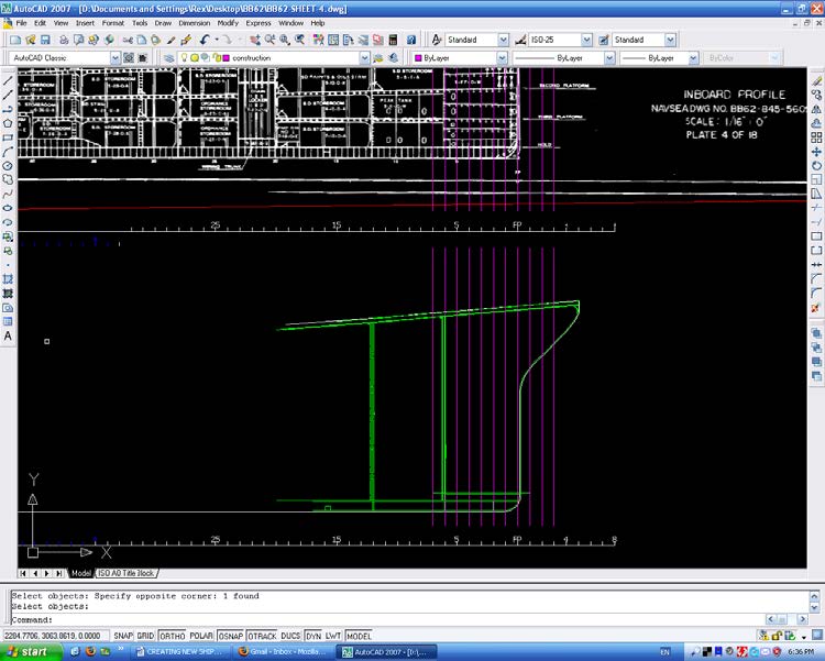
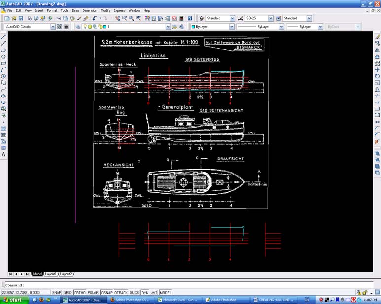
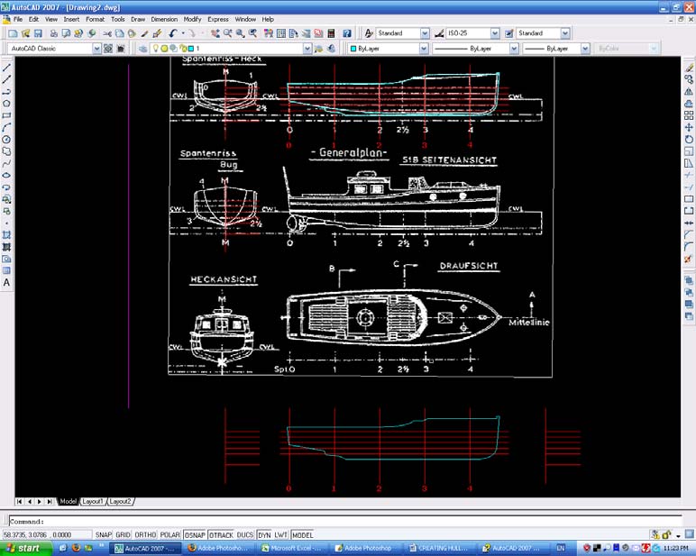
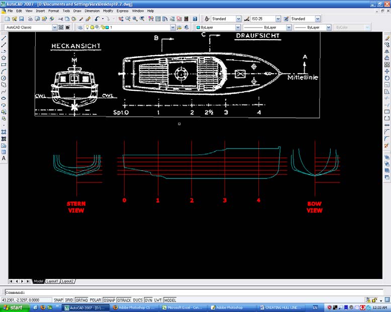
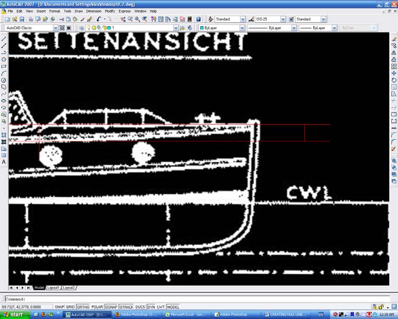
Following the steps outlined in Part 1, insert the image into AutoCAD. Then rotate and change scale to full size (scale 1:1). The example below shows what we should have. I have moved the bow view (second down on the left hand side) to line up with the stern view, making it easier to follow. Notice I have drawn the Base Line and Station lines (shown in red). I have also drawn the reference line down the left hand side (shown in magenta) and copied the reference line to where I will place the new drawing.

2 Draw Hull Lines
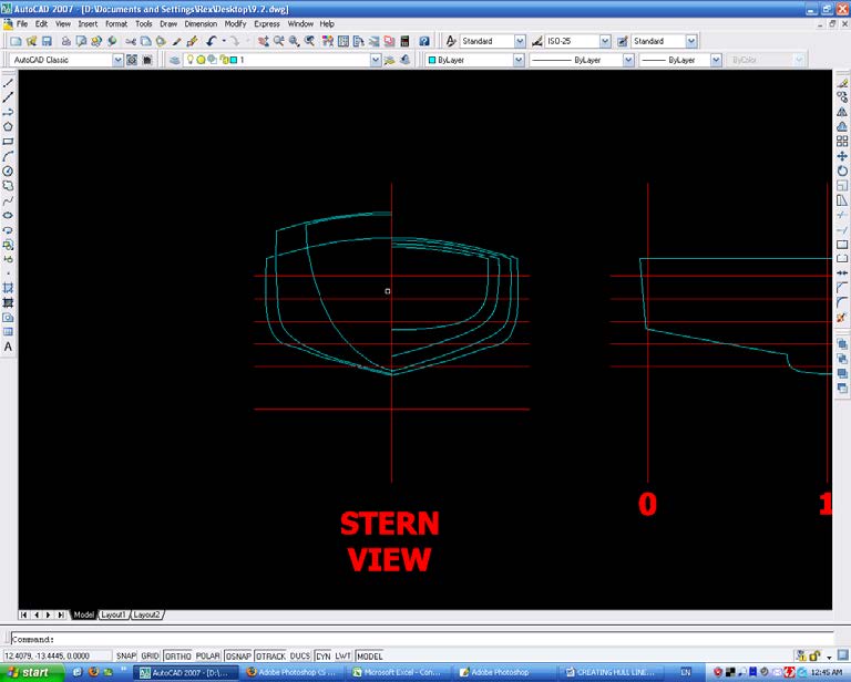
Copy the elevation of the boat and transfer it to the new drawing underneath. Start by transferring all the straight lines only – this will give us a reference for our splined lines. These straight lines are shown below colored cyan. Next, we will copy and transfer down the curved lines, but before we do that I will explain splines.
There are 2 types of splines used in AutoCAD. The first is a B Spline, where "a curve passes near a given set of control points". The second a Bezier Curve, where "a curve passes through a given set of control points". We will using B splines. There are a few simple rules to follow. When the curve is long and gentle, use the fewest number of points to achieve the curve and always add points where the curve changes its direction. Where the curve is convoluted, put points wherever there is a small change. This is illustrated below:
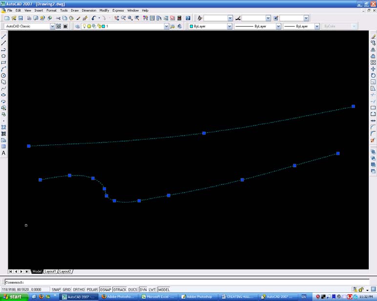
We can modify the curve by selecting then dragging the control points (known as ‘grips’ and shown in blue above). Remember to hit the F8 key to turn ortho off, or we cannot move the control points small distances in any given direction. Practice generating spline curves as they are often used on ships line drawings. It is interesting to note that in the past special wooden curves were used but the accuracy was nowhere near what we can achieve today with computers. In addition, hulls were never as accurate as the drawings – wooden ships were ‘handed’ as there were considerable differences between the hull profiles on the port and starboard sides. Anyway, we should end up with a drawing as below:
Next, do exactly the same with the frame lines, starting with the lines on the bow view. (We will only draw lines for one side, not both as shown on the original image).

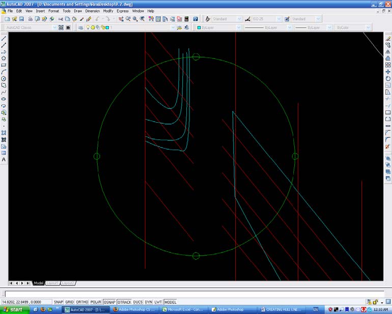
Check the fairness of the lines using the View, Orbit, Free Orbit command. This lets us ‘spin’ the view to get a better idea of the fairness by aligning the view with the line. On the example below, we can see immediately that the lower line is not true. We can grab the ‘grips’ and modify this curve in this view as well.
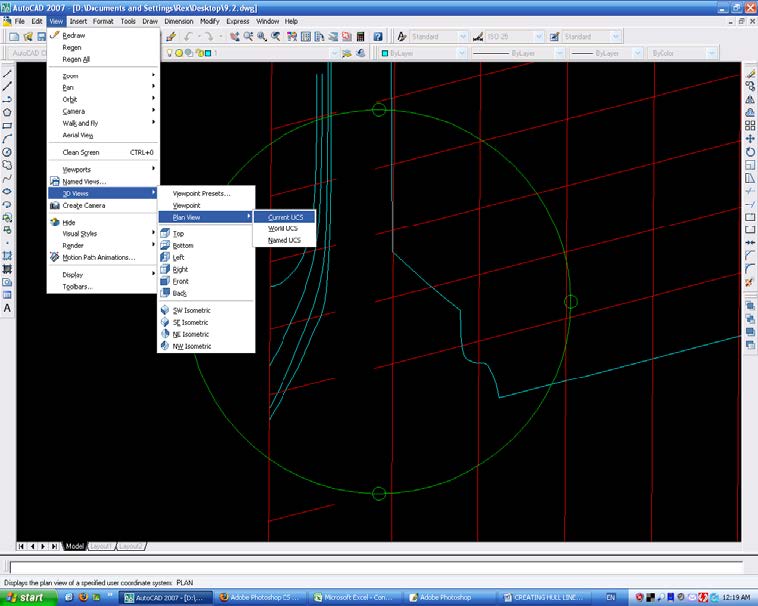
When we have ‘faired up all the lines, we revert back to the original view by selecting View, 3D Views, Plan View, Current UCS. This is shown below.
Finally, mirror all the lines on both end views. We now have an accurate profile of the outside of the hull. Next we will add the deck camber line.
Go back to the starboard elevation, draw 2 lines from the deck top and the deck bottom – the distance between will be the camber on the centerline.
Transfer this to the end view. Then copy across the bow lines to the stern view and we have a set of lines. As we are going to use these lines for a model, there remain just two more steps: rescale the drawing to our model's scale and offset the hull and deck thickness for our frames. At this stage the drawing should look like this:
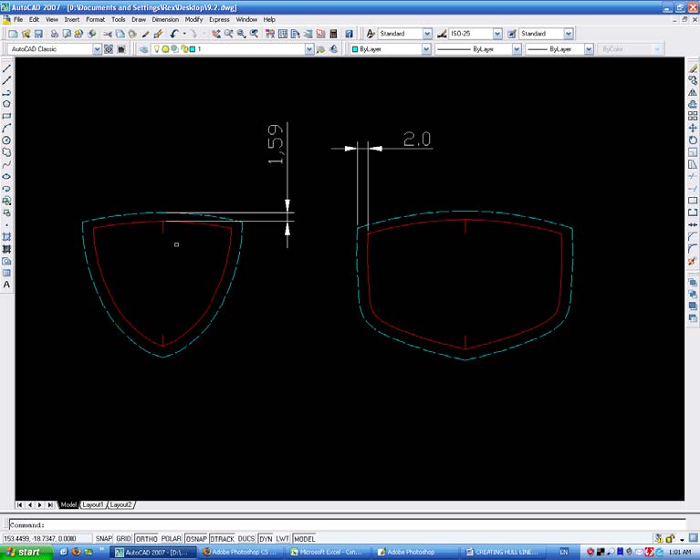
The drawing is now rescaled to 1/32 or whatever scale we want our model to be). Finally, we offset by the thickness of our hull on the sides (2.0mm), and the thickness of our deck at the top (1.59mm). I have done 2 frames to show this. If we wish, we can go one step further and mark the cut-out’s on the centerline (keel) section and the corresponding cut-out’s on the frames. As a matter of interest, the boat is a 9.2m launch from KM Bismarck.
PART 3: DRAWING SUPERSTRUCTURES FROM EXISTING IMAGE FILES
1 Insert Image into AutoCAD and Draw Reference Lines
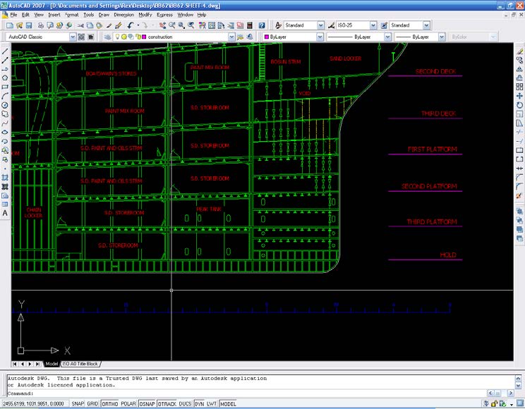
Following the steps outlined in Part 1, insert rotate and scale the image into AutoCAD. The example below shows what we should have. We don’t need many reference lines here: one on the centerline and one on a station line (shown in red). We have also drawn the reference line down the left side (shown in magenta), where we will copy to and place the new drawing.
2 Draw Outlines
Copy the plan view outline and the starboard view outline to the new drawing below. At this point, you will notice that frequently the lines don’t line up. This is because all drawings were hand drawn and drafting skills varied. Where we need to adjust lines, always try to use a station line as the reference and adjust accordingly.

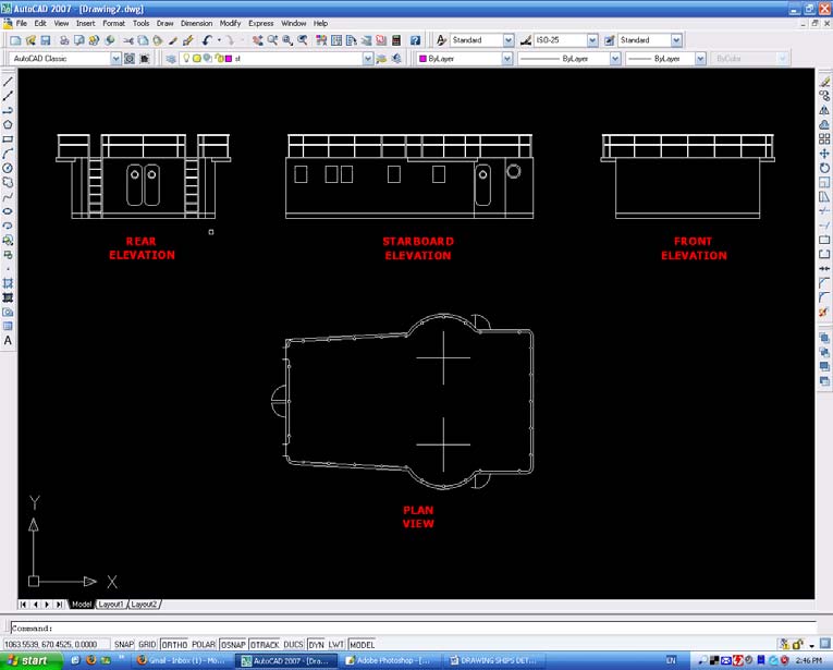
Next draw a line at 45° to our base line and transfer lines across (shown yellow) to create the third view. Mirror the half view, then do the same for the other end view. We now have the outline of the deckhouse in all three views.

Finally, add all the other smaller details, using the steps above. We can also copy across the part views giving positions if we want to create outlines to help in our modeling. As we have been drawing in full size, we now need to decide if we will want to save the detail for use in other drawings. If we don’t want to save the detail, rescale the drawing to the model scale, save and print. On the other hand, we may decide to save the plans as a block, so we can reuse them in another drawing.
3 Draw Blocks
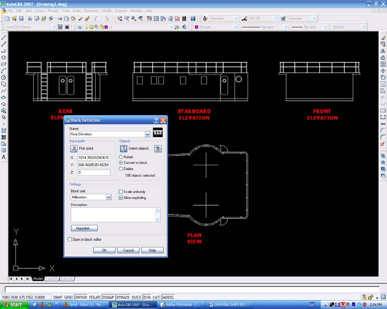
We will make the deckhouse using 5 blocks, one each for the individual views and one large block comprised of all the other blocks. These blocks will be called Rear Elevation, Starboard Elevation, Front Elevation and Plan View. The final block will be called Deckhouse. This lets us manipulate the blocks more easily at some point in the future if we wish to re-use them.
4 Draw Templates
We need to create templates for the roof and walls so they can cut them out of our building material. Explode all the blocks, then copy the roof plan and erase everything but the outline. I always add centerline crosses to show me where the stanchions are located. Finally, do the same for the wall elevations. You can separate the individual walls or cut them out as one. Both are illustrated below.
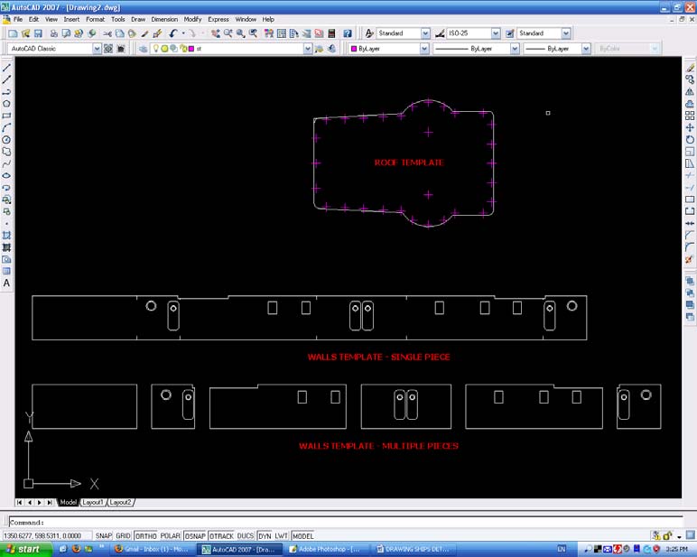
Rescale the drawing to our model scale, save and print. If the parts are complicated, I print the template out on paper with a sticky side; simply peel paper off the material after it has been cut out. You could also offset the card thickness on the roof plan and re-use as a base. This is especially useful if modeling a large superstructure such as that found on a battleship.
As a matter of interest, the boat is a WWII German minesweeper.
PART 4: DRAWING SHIPS SMALLER DETAILS FROM EXISTING IMAGE FILES
1 Insert Images into AutoCAD and Draw Reference Lines
Frequently, details of smaller parts are found scattered over different images , so we need to organize these on our drawing sheet where they can be more easily used. It is therefore important that we get both the scales and the orientation correct for all these parts. The screenshot below shows all the images inserted into AutoCAD (following the steps outlined in Part 1) and in the rough position I want them for redrawing later. Notice they are also of very different quality due to the scanning qualities.
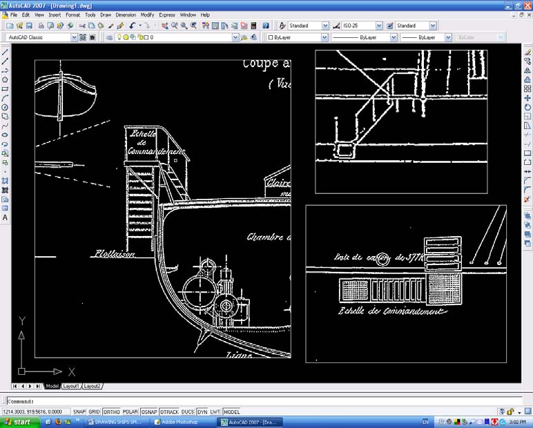
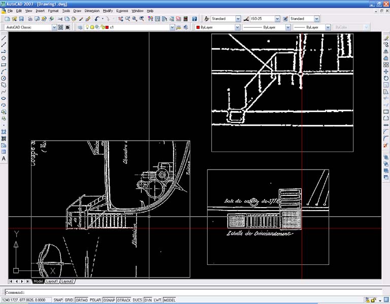
I tend to insert all the images (after I have cropped them to show only the parts we are interested in) and set them along common horizontal and vertical baselines. You will have to rescale each separate image to match that of the first image. Do not worry about overall scales at this moment as we will rescale all the views later on. Then they will need to be rotated to bring them all square on to the first (or main) image, they are ALL rotated to bring them square to the drawing page. It doesn’t really matter which order you do this in, but check that they all line up! We are now ready to redraw the parts we want to generate our new view. The picture below shows all the views scaled and rotated. We don’t need many reference lines here – 2 will do. One on the lower edge and one on the forward edge. We then need to draw the reference line down the left hand side to where we will copy to and place the new drawing.
2 Draw Outlines
Copy the plan view outline and the starboard view outline to the new drawing below. We will need to realign lines, always use our baselines as a reference and adjust accordingly. It is worth mentioning here the Divide command, which evenly divides a line into any number of equally spaced segments.
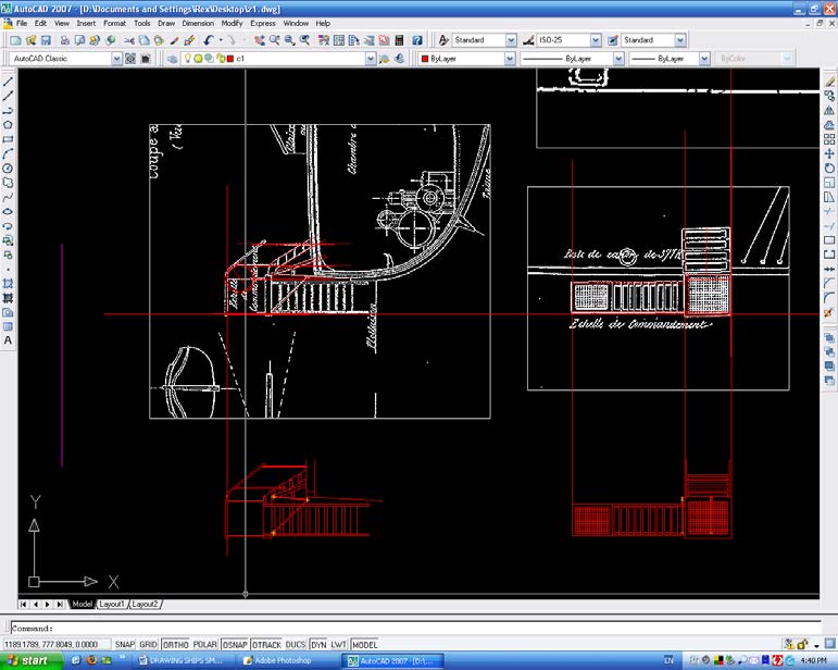
We now have the outline of the accommodation ladder in two views, and it is an easy task to generate the third view from these and we can add all the smaller ancillary details. The final completed drawing is shown below:
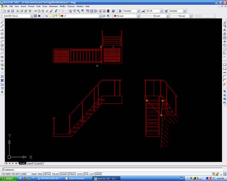
We now have the detail in all three views. Rescale to the drawing full size, using the steps shown in Part 1 and save.
As a matter of interest, the boat is the French Zelee, sister of the Atrolobe of Antarctic fame.
|
© 2023 The Nautical Research Guild, Inc. Nautical Research Guild ® and the NRG logo are Registered Trademarks, and belong to the Nautical Research Guild (United States Patent and Trademark Office: No. 6,999,236 & No. 6,999,237, registered March 14, 2023)
|
![]()
© 2020 The Nautical Research Guild, Inc.
![]()